
| (prev) | (top) | (next) |
In an RL circuit, the voltage drop across the inductor (from Faraday's law) is L dI/dt; this means that its solutions are isomorphic to those of the
RC circuit with the substitutions:
V - q / C - I R = 0 → (q - C V) = - R C dq / dt
The energy density of a magnetic field is B2 /
(2 μ) (this result can be computed using a solenoid:
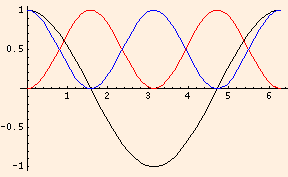
The simple harmonic oscillator is a conservative system. In this graph, q(t) is in black, q2 / 2 C is in blue and L I2 / 2 is in red:
If R > √ (4 L / C), ω is imaginary and the circuit is said to be overdamped.
For small oscillations of the pendulum (with x = L θ):
we have
d2θ/dt2 + (g / L) θ = 0
Oscillators
L = ΦB / I,
is measured in Henrys (1 H ≡ 1 V s / A). It depends only on the geometry of the inductor and the permeability.
V - I R - L dI / dt = 0 → (I - V / R) = - (L / R) dI / dt
L I2 / 2 / (area * length) = B * N * I / (2 length)
but it is true in general).
= B * B * N / (μ N / length * 2 * length)
M12 = Φ1 → 2 / I1,
where Φ1 → 2 is the flux induced in inductor 2 by inductor 1. The induced potential is - M12 dI1/dt.
q / C + L d2q/dt2 = 0.
This has the general solution of a simple harmonic oscillator:
q(t) = A cos (ω t + φ),
where the angular frequency ω = 1 / √ (L C), having units of 1 / s.
The argument of the cosine function is called the phase, φ is
the phase angle, which is determined by the initial conditions, and A is the
amplitude, in this case the maximum charge.
The period T = 2 π / ω and the
frequency ν = 1 / T, measured in
Hertz (Hz).
R dq/dt + q / C + L d2q/dt2 = 0.
If R < √ (4 L / C), it has real solutions
q(t) = A e - R t / (2 L) cos (ω t + φ)
where ω = √ (1 / (L C) - (R / (2 L))2).
m d2x/dt2 + k x + b dx/dt = 0
with the substitutions:
Remember that x represents the displacement from the equilibrium position.
The potential difference supplied by a battery is analogous to an external driving force.
sin θ = Σk = 0∞ (-1)k θ2k + 1 /
(2k + 1)!
so for small angles sin θ ≈ θ.
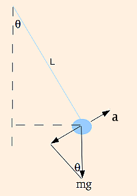
m d2x/dt2 + m g sin θ = 0
which is a simple harmonic oscillator with angular frequency √ (g / L).
keffective = 1 / (1 / k1 + 1 / k2)
and the effective spring constant for springs in parallel is simply the sum of the spring constants. This is due to the fact that in the
isomorphism, charge is related to displacement and voltage drop is related to force. For the two capacitors in series, their charges are equal and their voltages
add; for the two springs in series, their displacements add while the force (m g) is the same for both.
| (prev) | (top) | (next) |
©2011, Kenneth R. Koehler. All Rights Reserved. This document may be freely reproduced provided that this copyright notice is included.
Please send comments or suggestions to the author.