These gadgets where known as "siege engines", and the men who designed them were the first "engineers". Since my calculus-based physics class is largely made up of engineering students, it seemed a natural lab project for them as we study mechanics. So over the course of ten weeks, I have them design, build and test a trebuchet made from 1/2 inch PVC. Of course, I had built one for myself as I designed the project, and after watching a number of groups try various designs, with varying success, I got curious as to how the project would scale up.
So I drew up a design based on 3 inch PVC, made a shopping list, and headed to my local home center. As I stacked PVC pipe onto my shopping cart, I began to get the feeling that the whole idea was crazy and a waste of time (which it probably was). Then I decided, "No guts, no glory!" Shortly thereafter, nine 10 foot lengths of 3 inch PVC fell off my cart, making a grand clatter... And here I am, over a year later and after many delays, telling you the story in case you ever get bit by the same crazy bug.
This list doesn't include the things which I purchased and subsequently destroyed in testing. It also doesn't include tools purchased for the project (such as a 1 1/8 inch drill bit).
Count Item Price 10 3 inch by 10 foot PVC pipe, cut as follows: 69.70 1 x 10 foot (F) 8 x 4 foot (C) 2 x 4 foot 2 inches (D) 8 x 6 inches (D, G) 4 x 4 foot 10 1/2 inches (E) 4 x 3 foot 8 1/2 inches (B) 2 x 4 1/2 inches (G) 4 x 3 1/4 inches (G) (and 14 small pieces cut to fit) 10 board feet 1 3/4 inch thick yellow poplar, 125 inches long 29.00 16 3 inch PVC sanitary tee 51.32 8 3 inch PVC 90 degree elbow 18.96 2 3 inch by 3 inch by 2 inch PVC 90 with side outlet (A) 18.76 2 2 inch by 3/4 inch PVC bushing (A) 2.06 1 3/4 inch by 48 inch galvanized pipe (A) (1 1/16 inch outer diameter) 12.00 1 3/4 inch by 60 inch threaded steel rod (A) 17.97 16 6 inch by 1.5 inch plastic wheel 70.08 with 1/2 inch hub, nylon bearing, load rated 50 pounds each 8 3/8 inch by 10 inch hex bolt 11.76 8 3/8 inch nuts (on hand) 1 1/4 inch by 50 foot nylon twist rope 9.49 1 bath towel with "rope channels" sewn in (on hand) 2 8 oz. PVC cement 10.94 2 1 1/4 inch 2 hole EMT strap 0.72 4 1 1/2 by 1 1/2 by 12 inch 14 gauge plated slotted angle 11.88 6 1/4 inch by 6 inch hex bolt (on hand) 6 1/4 inch nuts (on hand) 12 washers (on hand) 2 16 foot ratchet tie-down 23.94 2 10 foot ratchet tie-down 6.99 10 3 foot bungee cords 14.85 120 pounds weights (inner diameter 2 1/8 inches) (on hand) 1 short barbell (on hand) 8 1 inch rubber balls (on hand) duct tape (on hand) total cost before tax 380.42 The letters in parentheses indicate where each part is used (see below).
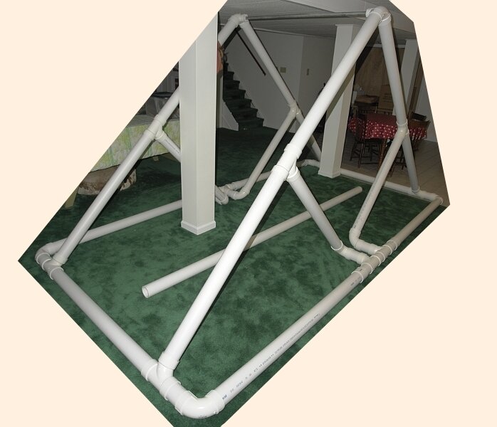
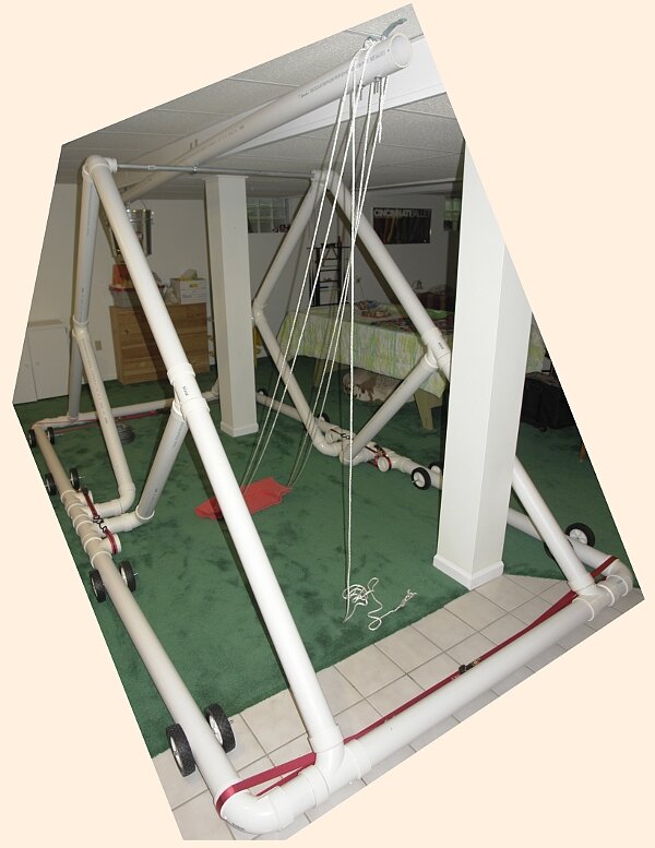
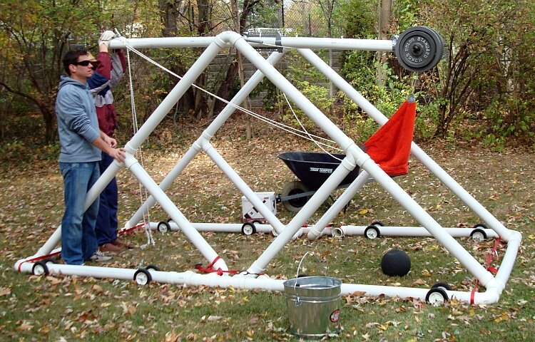
This design is intended to be partially glued, breaking down into 18 pieces for easy (!) transportation. But after gluing, I discovered that the structure was still too flexible; I was pretty sure that under load it would pull apart. So the area of the base at the central supports was slightly redesigned, and a set of ratchet tie-downs were added to hold the base together during operation. The final design (below) is much more stable.
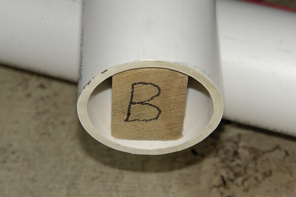
The base breaks down into eight pre-glued sections. Each of those sections includes a pair of fittings (sanitary tees or 90 degree elbows) with axes that have to be parallel for the pieces to fit together properly. But since by design, each section only has two such fittings, it was only necessary to glue them on a flat table, making sure the fittings rested flat on the table during gluing:
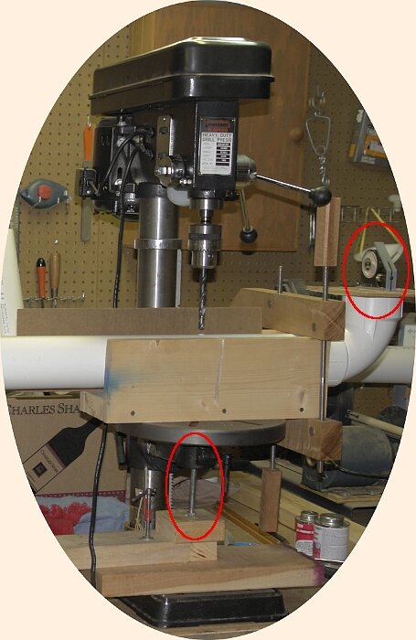
Drilling the holes for the wheel axles (the hex bolts) and the EMT straps along the throwing arm was slightly more problematic. It was obvious to me from my experiences with the 1/2 inch model that I had to use a drill press in order to get the holes parallel to each other and perpendicular to the center of the pipe. But the "3" in "3 inch PVC" is the inner diameter of the pipe. So in order to drill a single hole all the way through the pipe, your drill press must have a four inch travel. And of course mine only travels three inches.
So I fashioned a jig to hold the pipe in place, drilled the "top" hole, and then turned the pipe over. Running a bolt up through the center of the jig
(lower red oval) and into the "top" hole, I was able to make sure that the bottom hole would be positioned correctly along the pipe axis.
By using a level across
the end of the pipe (which had already been glued on, red oval on the right), I was able to ensure that the "bottom" hole would be
parallel to the "top" one.
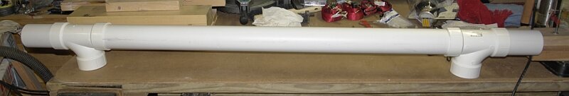
During initial load testing, the throwing arm flexed four to six inches with 45 pounds of counterweight. To make it more rigid, I enlisted some spectacular aid from Mark Cheatham and his amazing wood shop. I purchased a 125 inch length of 1 3/4 inch thick yellow poplar, and Mark finished one edge with his jointer, ripped it to just under 2 5/8 inches, cut five inches off the end, and chamfered it to fit inside the PVC:
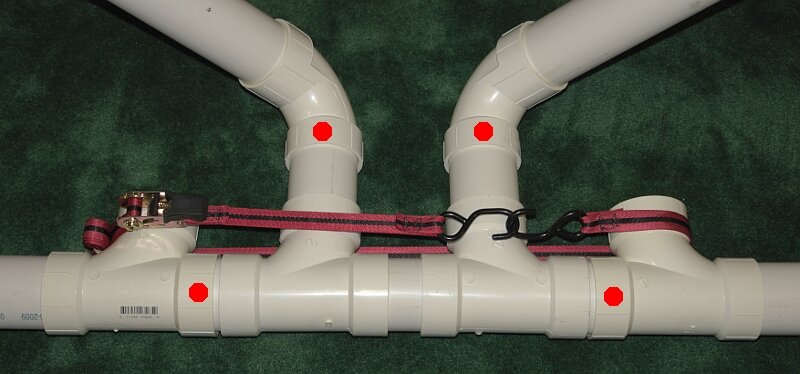
Note the modified center supports. The joints marked with red dots are not glued; all other joints are. The two sanitary tees (at left and right) were added to the initial design to provide anchors for the come-alongs:
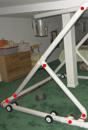
This closeup shows one quadrant of the trebuchet. Again, the joints marked by red dots are not glued; all other joints are. The four quadrants are symmetrical, and all corresponding parts of each quadrant are interchangeable.
Here are the individual pieces of a quadrant (labeled B, C and E) together with the center support (G), the end beam (D), the throwing arm (F) and the axle (A):
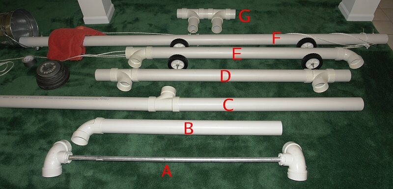
There are, of course, four each of B, C and E, and two each of D and G. All joints in these parts are glued.
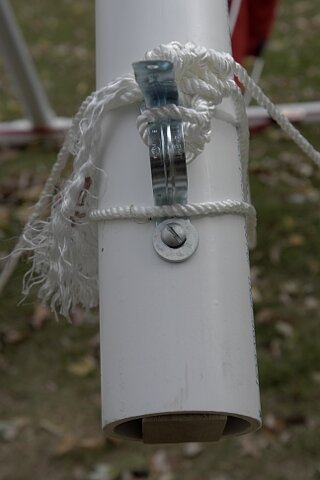
This is a closeup of the attachment of the sling to the throwing arm. One end of the sling is fastened to the EMT strap, and the loop on the other end is allowed to slide off the straightened strap during throwing. The latter can be bent (through trial and error) to achieve the optimal range:
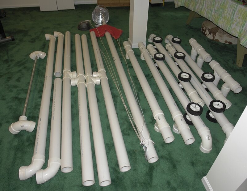
The whole thing, broken down for transportation, is shown here:
I had originally intended to mount the axle through a hole in the throwing arm, but realized pretty quickly that the stress would crack the PVC (with a 1 and 1/8 inch hole through the center, the pipe would have about one third less material to support the counterweight and payload). But now that I had inserted the poplar support beam through the throwing arm, it should be strong enough to take it. I added a couple of angle irons along the center of the arm to reinforce it:
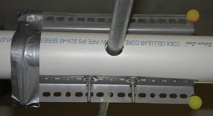
with rubber balls (held in place by the handyman's friend) to cushion the ends of the angle irons.
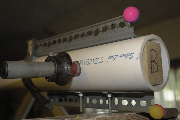
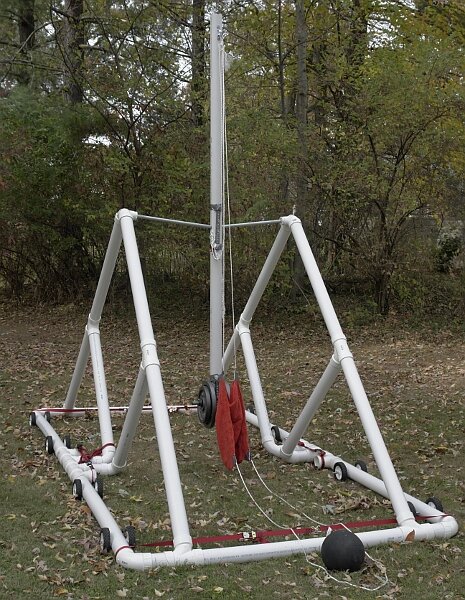
In addition, it was fairly obvious (given that the basketball went nowhere) that the additional weight of the support beam necessitates additional counterweight. So I drilled a hole through the end of the throwing arm, where the bucket was attached, and mounted the counterweights on a short barbell (donated by my wife's cousin Jim Barth) inserted into the hole:
I lost the free swing of the bucket, which allowed the counterweight to move in a more nearly vertical path, but gained a stronger mount for the counterweight, and eliminated the freedom of movement which caused the bucket to fail.
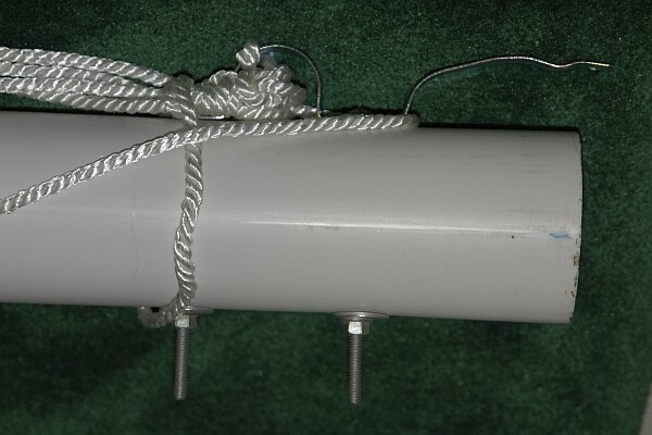
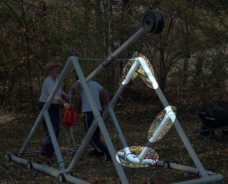
It looks unlikely that I will be able to use more weight than that. We also found that the sling slid too easily on the rope, and used the handyman's friend to solve that problem. I settled on a release mechanism that uses two lengths of rope tied to the bracket on the throwing arm, each one fed under the center of the frame. That allows one person on each side to hold the throwing arm in a nearly vertical position before release:

And then we found the next design flaw: the axle was not strong enough to support the throwing arm when it is released from that height:
In addition, as the arm swung, the frame flexed enough to allow several of the unglued joints to come apart; here is an 11 second movie (1.8 MB) of that test. Finally, we found that the sling ropes were too long, and the sling was too large: it was holding on to the projectile. But as it turns out, these problems were not fatal.
Test run three included a series of 10 throws. The first six were unsuccessful, but for a change our problem was not structural failure. Instead, I encountered the same problem that plagues so many of my student teams: it is very difficult to adjust the sling and the EMT strap for the correct release angle. We altered the sling in a variety of ways with duct tape, but repeatedly suffered from late releases, throwing the basketball relatively violently into the ground. In most instances it never left the sling. But I had watched a number of enterprising students in my labs try variations on the traditional release methods, and in designs particularly prone to this problem, their solution was usually to throw the entire sling along with the projectile. Adopting their plan, and with slight modifications to the release mechanism, we had our first two successes. Here is
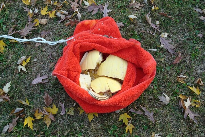
So we loaded up a pumpkin and promptly threw it backward! (a 6 second movie, 2.9 MB) It turns out that the much heavier pumpkin required an entirely different release method. We shortened the sling slightly, and moved the EMT strap to the other side. Whereupon the sling caught on the restraining bolt and hit the ground with a great deal of vigor (a 24 second movie, 8.3 MB):
At this stage we were all tuckered out. When my students use 2.4 kg of counterweight on a 24 inch throwing arm, they have to exert 2.4 pounds of force to lift the counterweight into throwing position, costing them a little over 3 Joules of energy. Our monster requires 120 pounds of force, and over 260 Joules of energy every time we tried to throw. After a handful of throws it becomes a tiresome endeavor, and adjusting the payload with 120 pounds hanging five feet over your head becomes more and more worrisome...
I want to thank my nephew Adam Bare and his wife Stephanie, who were a tremendous help during these tests; Adam provided some much-needed muscle, and Stephanie helped my wife Mary with the videography. Thanks also to neighbor Nick Bunch for additional muscle while we were figuring our how to make something fly.
But beyond that, scaling the project up introduces a host of new problems. Flexibility increases faster than length, necessitating additional stiffening (the poplar beam). This drives the weight up, requiring a larger counterweight to get the same release speed. This in turn makes it harder to use, and more dangerous.
©2010, Kenneth R. Koehler. All Rights Reserved. This document may be freely reproduced provided that this copyright notice is included.
Please send comments or suggestions to the author.