
If we recall the most general expression for the phase of an oscillator, we see at once that waves can also travel:
y(x,t) = A sin (kx + ωt + δ).To simplify things, we will set the phase angle equal to zero and rewrite this equation as
y(x,t) = A sin (k (x + (ω/k)t)).Compare this to the form of a function which undergoes translation: the transformation
y(x) -> y(x + a)moves the function to the left a units:
This shows us that our traveling wave is simply an ordinary sine wave which is being translated by an amount depending on time. As we saw in the last section, w/k is the speed of the wave which in this case is traveling to the left:
A wave which travels to the right is described by
y(x,t) = A sin (kx - ωt).We say that a traveling wave propagates through the medium. Sound is a longitudinal wave: the wave function describes changes in air pressure which are parallel to the direction the wave is traveling. Water waves, seismic waves and light waves are all transverse: the displacement of the water, ground or electric and magnetic fields are all perpendicular to the direction the wave is traveling. The foremost edge of a traveling wave is called the wave front, and plays an important role in our understanding of wave behavior.
Huygens' Principle states that each point on a wave front acts like a source for the next wave front. It is as if there is a tiny harmonic oscillator at every point in space and the vibration of one oscillator along a traveling wave causes the next one in the direction of travel to begin vibrating:
Each oscillator generates a hemispherical wave disturbance in the direction of travel, which we have shown here in cross section as semicircles. The wave front is tangent to the semicircles at any given time.
We see that the angle of reflection is equal to the angle of the incident rays.
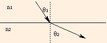
Do the following experiment as you are reading this: place a pencil in a glass of water. The pencil appears to be broken because the speed of light is different in the water than in the air: this is called refraction. If we write the speed of light in an arbitrary medium as
where again the wave fronts are drawn at equal times. The change in direction is described by Snell's Law:
Note that for any angle greater than the "critical angle"
It is the refraction of light which makes possible both vision and vision correction. A ray of light as it traverses corrective lenses and the eye is refracted:
Recall the wave demonstration applet in the previous section. Set the black and blue waves to the same mode number and observe the red superposition wave as you vary the blue wave phase angle. When the phase angle is zero, the black and blue waves are said to be in phase and constructively interfere. When the phase angle is π or -π, the superposition wave has an amplitude of zero and the black and blue waves are said to be out of phase: they destructively interfere. The interference of coherent waves (which start out in phase) lies at the heart of the quintessential wave phenomenon: diffraction.
We start by illustrating how interference works in two dimensions with this applet, which shows the superposition of two waves from
sources at the bottom of the image. The white spots are where the waves
constructively superpose and are in phase, and the black spots are where the waves destructively superpose and are
out of phase:
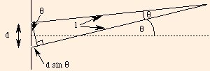
Suppose that a beam of light is incident on a surface with two slits in it (separated by a distance d). Huygens' principle states that the two slits will act as coherent sources. These correspond to the applet above, with equal frequencies and zero phase angle. When the light rays from these two sources interfere at the screen (a distance L away from the slits), one will have traveled farther than the other:
The angles are approximately equal, as are the hypotenuse and adjacent sides of the large triangle, if the angle is small. This is true since the length L is usually much greater than the distance between the slits. The difference in length of the two rays from the slits to their point of intersection is d sin θ. When this length difference is an integral number of wavelengths:
we can write their locations as
For constant wavelength, an increase in d moves the maxima closer together (the angle must decrease for a given m) and washes the pattern out. For a constant slit separation, increasing the wavelength spreads the pattern into a continuum (the angle must increase for a given m). In the limiting case, if d is less than λ, the condition for secondary maxima (m > 0) cannot be met. This illustrates the fact that resolution is limited by wavelength: you cannot distinguish two objects which are separated by less than one wavelength of the wave being used to image them.
While we have used light waves in this section to describe reflection, refraction and diffraction, is important to realize that sound waves share in all of these behaviors. For us, the primary difference between the two is simply their speeds of propagation. We can compute the positions of maxima and minima of light intensity given the geometry of the experiment, the frequency of the wave and the index of refraction of the medium:
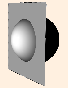
One result of Huygens' Principle provides us with a unique opportunity to "see" infinity. Consider a spherical mirror, formed by "slicing" off
a spherical segment of a reflecting sphere of radius r:
For a convex mirror (looking into the outside of the spherical segment), the magnification of the image (the ratio of the image size to the object size)
is equal to 1 when the object touches the mirror, and reduces to 0 as the object recedes to infinity; and the image is always "right-side-up".
But for a concave mirror (looking into the inside of the spherical segment), something very interesting happens.
Huygens' Principle leads us to discover that the magnification M is given by
As the object continues to recede, the image is inverted (M < 0), and slowly shrinks in magnification. Try this
with the inside of a highly polished serving spoon, or some other reflecting concave surface.
And in a coincidence of physics, the magnification of a concave mirror "mirrors" the form of the radial singularity
(where changes in radial distance go to infinity) of a static black hole of mass M:
The next section introduces the magnetic field.
©2013, Kenneth R. Koehler. All Rights Reserved. This document may be freely reproduced provided that this copyright notice is included.
Please send comments or suggestions to the author.
Huygens' Principle
We found that the energy of an oscillator is proportional to the square of its amplitude. For a spherical wave, that energy is
evenly distributed on the surface of an ever-expanding sphere. We define the intensity to be the ratio of the power carried by the wave
to the surface area of the spherical wave front:
Consider the reflection of an image in a mirror. For simplicity, we will follow just two rays of light from the image, showing the incoming wave fronts in red and the outgoing wave fronts in blue at equal time intervals:
I = P / (4 π r2).
From this we can see that while the total energy in the wave is constant (ignoring dissipative effects), the intensity drops off as 1 / r2.
v = c / n,
n is called the index of refraction; it is always greater than 1 and so the speed of light in any material medium is always less than the speed of light in a vacuum. In general, the index of refraction is a function of wavelength; for sound,
while for light (of wavelength 589.3 nm),
Since the speed of light is less in water than in air, the wave fronts change direction when crossing from one medium to the other:
n1 sin θ1 = n2 sin θ2
where the angles are measured from the normal to the interface between the two media:
θ c = arcsin (n 2 / n 1)
Snell's Law is not applicable; instead of refraction, there is total internal reflection, which means that the ray
(and hence the wave) does not cross the boundary.
The depth, shape and index of refraction of each medium determines the degree to which the rays of light are bent, and hence the focal point: where the image is in focus. The focal point should be just short of the retinal surface; if it is too close to the eye's lens, the eye is near-sighted and requires a divergent, defocusing corrective lens; if it is on the retinal surface, the world appears as a bright point of light; and if it is behind the retinal surface, the eye is far-sighted and requires a convergent, focusing corrective lens.
Careful application of Snell's Law will enable you to determine whether concave or convex lenses are focusing or defocusing.
Interference
d sin θ = m λ,
the phase difference is
k Δx = (2 π / λ) * m λ
so the waves are in phase, and we have constructive interference and a bright spot at the point of intersection (at x = L sin θ). When this length difference is a wavelength times an integer plus one half:
= 2 π m,
d sin θ = (m + 1/2) λ,
the phase difference is
k Δx = (2 π / λ) * (m + 1/2) λ
so the waves are π radians out of phase, and we have destructive interference with a dark spot at the intersection. If we label the minima and maxima with
a number "a" as follows:
= 2 π m + π,
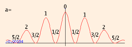
x = a L λ / d.
The first applet plots the intensity as a function of position, while the second applet provides a visual illustration of the actual diffraction pattern:
M = 1 / (1 - 2 O / r)
where O is the distance from the object to the surface of the mirror. M is still 1 when the object touches the mirror, and the image is still right-side-up.
But as the object recedes toward a distance r/2 from the mirror, the magnification approaches infinity (here, r = 2m):
ds2 = dr2 / (1 - 2 M / r)
Here, as an object approaches r=2M, a far-away observer sees any change in position as taking infinitely long: the inward-falling object never appears to
gets closer than 2M, even though the object itself has long since crossed that boundary. We will discuss this issue in more detail
later (note that to simplify the equation, we have changed the units of M to meters by multiplying the mass
by G/c2, where c is the speed of light).