
Our brief mention of the changing electric and magnetic fields in radio and light waves has already led the discerning reader to conclude that electric fields and magnetic fields are closely related. In fact, much of what we have learned about the electric field applies to magnetic fields as well:
But whereas the electric field is caused by the presence of electric charges, the source of the magnetic field is a current element:
I l,the product of a current and its length. And while the direction of the electric field is radial relative to the source, the direction of the magnetic field is a three-dimensional function of the current direction and the field point called the cross product.
We have already discussed the x and y components of forces in two dimensions, on a plane. In three dimensions, there is a z component as well which is perpendicular to the x-y plane. With the usual orientation of the x-y plane:
the positive z direction points out of the page towards you and the negative z direction points into the page away from you.
The cross product of two directions always yields a third direction which is perpendicular to the plane of the previous two as follows:
The cross product of any direction with itself is of course zero. We can remember this definition with the help of a little mathematics.
x ⊗ y -> z y ⊗ x -> -z y ⊗ z -> x z ⊗ y -> -x z ⊗ x -> y x ⊗ z -> -y
The canonical order of coordinates in three dimensions is
In any coordinate system the canonical ordering provides us with a consistent definition of the cross product by analogy with the Cartesian definition above. Consider the cylindrical coordinate system in three dimensions:
The location of any point in space is given by the perpendicular distance from the z axis:
Suppose the current element which is the source of our magnetic field lies along the z axis and the current is flowing in the positive z direction (recall that this means the negative charge carriers are flowing in the opposite direction). Further suppose that the element extends from z = -l/2 to z = +l/2 and that the field point lies in the x-y plane. The field point is then in the ρ direction; this means that the direction of the magnetic field is tangent to the circle whose center is the origin and which passes through the field point:
We say that B is an axial field because of its axial symmetry with respect to its source. If the current were moving in the opposite direction, the direction of the magnetic field would be clockwise rather than counterclockwise. In either case, its direction is given by a "right hand rule":
The magnitude of the magnetic field is given by
The force exerted by B on a length l of test current I is
In further contrast with the case of the electric force, parallel currents attract and antiparallel currents repel.
We can see this because a test current element parallel to the z axis and at the field point in our picture above will experience a force
Consider a loop of current in the shape of a rectangle (the shape is actually not important) of length l and width w, lying in the x-y plane:
In a constant magnetic field (along the x axis), the current elements along the long sides will experience forces in the directions
y ⊗ x -> -z (for the right side)
In this applet, you will be given a test current element or a current loop, and asked to compute the magnitude and direction of its magnetic field. Then we will "turn on" a constant magnetic field, and you will compute the magnitude and direction of the force experienced by the test object (and if it is a loop, its potential energy).
Consider a charge q moving with velocity v in a magnetic field. Since q v has the same units as I L,
the moving charge acts like a current; the resulting magnetic force is called the Lorentz Force:
Recall that in uniform circular motion, the centripetal force
(which keeps the object moving in a circle) is perpendicular to the velocity. Assume that we have a constant B field which is
perpendicular to the plane of motion of a charged particle. The resultant force will be in the plane, but perpendicular to the velocity,
so the particle will travel in a circle. Equating the Lorentz Force to centripetal force, we have
The next section introduces quantum phenomena by way of Magnetic Resonance Imaging.
©2013, Kenneth R. Koehler. All Rights Reserved. This document may be freely reproduced provided that this copyright notice is included.
Please send comments or suggestions to the author.
{x, y, z}.
The cyclic permutations of this order are
{x, y, z}, {y, z, x} and {z, x, y},
which you see correspond to the positive cross products.
The anticyclic permutations are
{z, y, x}, {y, x, z} and {x, z, y},
which correspond to the negative cross products.
ρ = (x2 + y2)1/2,
the angular position on a cylinder concentric to the z axis and relative to the x axis:
φ = tan-1 (y / x),
(φ is the Greek letter phi), and
its z coordinate.
The canonical ordering of cylindrical coordinates is
{ρ, φ, z}
and so, for instance, the cross product of the z direction with the ρ direction is the φ direction: tangent to the cylinder at that point.
if you place your right thumb along the current element, the fingers of your right hand curl around the direction of the magnetic field.
B = μ I l / 4 π r 2,
where μ is the magnetic permeability and
μ0 = 4 π* 10-7 N / A 2
(an exact value) is the magnetic permeability of the vacuum. The SI unit of B is the Tesla (denoted by T), or N / A m. It is a very large unit; the Earth's magnetic field is typically a fraction times 10-4 T (10-4 T is also called 1 Gauss).
F = I l B sin θ,
where θ is the angle between B and the test current element; therefore if B is parallel to I, F is zero. The direction of F is given by the cross product of the direction of the test current element with the direction of the magnetic field, which means that F is perpendicular to both the test current element and the magnetic field. This situation is quite different from that of the electric and gravitational forces, which are parallel to their respective fields (pointing from one charge to another). It is as if pushing someone (analogous to the magnetic field) would not exert a force unless they were already moving (analogous to the moving charges in the current), and on top of that, a sideways push while they were running past you would cause them to rise into the air!
F = (I l) ⊗ B
in the direction
z ⊗ φ -> -ρ,
or toward the z axis. If the test current element were pointing in the -z direction, the force would be in the direction
-z ⊗ φ -> ρ,
or away from the z axis. It is clear that the relationship between magnetic fields and forces is inherently three dimensional, and quite counterintuitive.
Current Loops
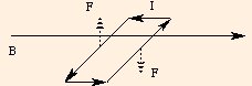
-y ⊗ x -> z (for the left side), and
(drawn with dashed arrows above). The forces experienced by the end current elements are initially zero, but as the loop moves, the forces will attempt to lengthen the loop; we will assume the loop is rigid and ignore those forces. The net forces have a magnitude of I l B, and cause a torque with lever arm w / 2:
τ = I l B w / 2 + I l B w / 2
where A is the area of the rectangle. In general, we write the torque as
= I A B,
τ = m B sin θ.
Here θ is the angle between B and the normal to the surface bounded by the loop, and
m = n I A
is called the magnetic moment of the loop: n is the number of turns in the loop, I is the current, and A is the surface area of the planar shape circumscribed by the loop. The direction of the magnetic moment which is normal to the loop, is found by another right hand rule:
curl the fingers of your right hand around the current flowing through the loop; your thumb will point in the direction of the magnetic moment.
The torque rotates the loop to line the magnetic moment up parallel to B; the axis of rotation due to the torque is given by yet another right hand rule
curl the fingers of your right hand around the direction of rotation; your thumb will point along the axis of rotation.
In the drawing above, the axis of rotation is in the y direction.
These right hand rules are of course consistent with the cross product
τ = m ⊗ B.
The magnetic potential energy of the loop in the magnetic field is
U = - m B cos θ,
and we see that the process of aligning the moment with the external magnetic field B minimizes the potential energy of the loop: as θ goes to 0, U reaches a minimum.
For a loop in the "a-b" plane (where a and b can be x, y or z), the direction of positive rotation is counterclockwise, and the outward normal is a ⊗ b. So for a
counterclockwise loop, the magnetic moment will be in the a ⊗ b direction, while for a clockwise loop, the magnetic moment will be in the - a ⊗ b direction.
Note that the directions expected by the applet are "left", "right", "up", "down", "out" and "in".
F = q v B sin θ,
where θ is the angle between v and B. The direction of the force is perpendicular to both B and v.
m = r q B / v.
This gives us a way to measure the mass of an ion of known charge and velocity. The radius of the circle allows us to compute the mass of the ion.
This measurement technique is called mass spectroscopy.