Myelinated axons have small (1 μm long) interruptions in the insulating sheath every 2 mm. These interruptions are called Nodes of Ranvier, and are the sole places where ion transfer takes place. The density of ion channels is very large in these nodes: while there are only about 20 sodium channels per μm2 in a nonmyelinated axon, there are about 104 per μm2 at each Node of Ranvier in a myelinated axon.
The propagation of a nerve impulse along an axon begins when the synapses receives neurotransmitters from nerve endings nearby. The neuron then increases its internal potential, setting off a chain of events which is repeated for each Node of Ranvier as the nerve impulse "jumps" down the axon. This is known as saltatory conduction, and the change in potential at each node is called the action potential:
The vertical scale indicates the potential in mV while the horizontal scale indicates the position in mm. The animation makes it clear that the propagation of the impulse occurs much faster (10 nodes in 3.7 ms for this example) than the time scale of the action potential at a single node (2.5 ms). The widths of the individual action potentials in this animation have been narrowed for clarity; the propagation speed here is only 5.4 m/s (prove this, too!), which is an order of magnitude smaller than in mammals.
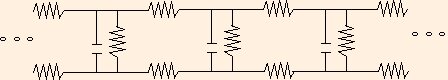
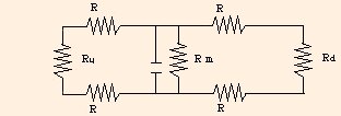
Each Node of Ranvier functions as a leaky capacitor: during the rise of the action potential, it stores positive charge inside the cell, while the passive ion channels allow some charge to leak out. Since the resistivity of the interior of the cell is large compared to metallic conductors, the interior of the cell between nodes acts as a resistor. The interstitial fluid between nodes acts like a resistor as well. So we can construct an incomplete electrical circuit analogous to the axon as follows
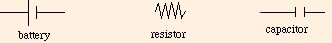
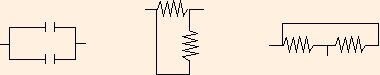
where the circuit elements are drawn using the standard symbols:
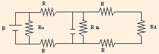
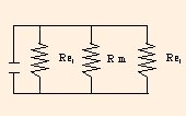
This analogy suffers in two ways: it is not a complete circuit, and it is complicated. We can simplify our discussion by considering a circuit which models a single node (with its surrounding environment):
but we still have to deal with the problem of simplifying collections of circuit elements. In the circuit above,
Our problem is now to simplify this circuit, and understand something about the consequences of the model.
Whenever two resistors or two capacitors are connected such that whatever current flows through one MUST flow through the other, we say that they are connected in series:
Two resistors in series are equivalent to a single resistor with a different value
Circuit Model of the Action Potential
Series and Parallel Circuit Elements

Req = R1 + R2.
We can see this as follows: conservation of energy tells us that the voltage drop across the equivalent resistor must be the sum of the voltage drops across the original two resistors. Since the same current flows through all of them, Ohm's Law:
V = I R
(which you derived using the applet in the previous section) tells us that
I Req = I R1 + I R2,
or
Req = R1 + R2.
If we equate the voltage with temperature and the resistance with the R-value, we see that Ohm's Law is analogous to heat conduction; it is essentially a diffusion equation for the drift of electrons.
Two capacitors in series are equivalent to a single capacitor with a value given by
1 / Ceq = 1 / C1 + 1 / C2.This is a result of conservation of charge. If a charge +Q is on the outer plate of C1, then a charge -Q must be on the outer plate of C2. The inner plates of the two capacitors of course have equal but opposite charges. Since capacitance is a ratio of charge to voltage, the voltage drop is given by the ratio of the charge to the capacitance. Conservation of energy again tells us that the voltage drop across the equivalent capacitor must be equal to the sum of the drops across the original two, and we have:
Q / Ceq = Q / C1 + Q / C2,or
1 / Ceq = 1 / C1 + 1 / C2.When two circuit elements are connected so that their ends are equipotential, or equivalently, the voltage drops across them MUST be identical, we say that they are connected in parallel:
Note that series and parallel have NOTHING to do with appearence. The connectivity of a circuit is a matter of topology, and is a function only of which wires connect which circuit elements. Appearence and wire lengths do not matter.
Two resistors in parallel are equivalent to a single resistor with a different value given by
We used conservation of charge and conservation of energy to deduce these equations. As applied to electrical circuits, these conservation principles are often stated as Kirchhoff's Laws:
Of course, there are many ways to connect circuit elements such that they are in neither series nor parallel. Here are two examples:
The two resistors are not in series, because some current which enters the left one may leave through the wire between them, and does not have to go through the one on the right. The two capacitors are not in parallel because the resistor between them causes a voltage drop, so that while the bottom ends of the capacitors are at the same potential, the top ends are not.
Now we are ready to simplify the node circuit. Rd and the downstream Rs are in series, so we can replace them with
and we can replace Ru and the upstream Rs by Req,1 as well. We now have
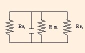
Since the upper wire is an equipotential, and the lower wire is also an equipotential, but at a different V, we can rearrange the circuit elements to form
The two Req,1s are then in parallel with Rm and can be replaced by
This is the simplest form of an RC circuit. If we carefully analyze the units of resistance and capacitance, we see that their product is
= C / (C / s)
= s!
We can now use the equations you constructed in the last section to calculate the voltage drops, currents and power loss for resistors, and the voltage drops, charge content and energy stored in capacitors. For instance, if we reinsert the battery in parallel with the last circuit (containing Req,2), a voltage of 30 mV (corresponding to the peak of the action potential) gives us a current of .882 μA and a power loss of 2.65 * 10-8 W through the resistor, and a charge on the fully charged capacitor of 3 * 10-11 C (corresponding to roughly 2 * 108 sodium ions). The energy stored in the capacitor at that point is 4.5 * 10-13 J.
We can then work our way backward through the simplification as follows:
Now that we've worked through a detailed example, we can see some practical results of Kirchhoff's Laws:
The following applet will give you some practice with these sorts of computations.
Note that while electrons cannot actually flow through a capacitor, as it is charging, electrons are
collecting on the negative side and leaving the positive side. This gives rise to a current "through" the capacitor. Initially the
current flows freely, but as the capacitor charges, the growing potential difference makes it harder for the electrons to redistribute. So
in the circuits shown in the applet above, when the battery is first placed in the circuit, most of the current flows through the capacitors.
As their stored charge increases, the current grows in the resistor network. The questions you are asked about the resistor currents
assume that the capacitors are fully charged, and that the current is only traveling through the resistors.
So what good are resistors in an electrical circuit?
At first glance it seems silly to want to lose energy in any physical system: it offends our sense that
efficiency is of paramount importance. The RC circuit we use as our
canonical example has an analog in a physical system: just as capacitors store energy, so too do
springs. And in that analogy, resistors act as friction,
which we are always trying to reduce or eliminate in practical applications.
In an RC circuit, the time constant is a measure of how fast the
capacitor is charged. After τ seconds, it is charged to 63.2% of capacity; after
2τ seconds, it is charged to 86.5%; after 3τ seconds, it is charged to
95%; after 4τ seconds, it is charged to 98.2%, and after 5τ seconds, it is charged to
99.3% of its capacity. While in principle it is never charged to 100% of its capacity, it effectively reaches full charge in
5τ seconds. But if R = 0, τ = 0. What happens if one tries to charge
(or discharge) a capacitor instantaneously? A small capacitor would melt, a large one would explode! The power applied to
it would be far more than it is physically able to survive.
Of course, RC circuits are used in many timing applications: the timing of the windshield wipers on your car is controlled by
an RC circuit. In addition, each bit in the DRAM (Dynamic Random Access Memory) in your computer is essentially an RC
circuit. In these applications it is very important that R be nonzero. There is another example of a
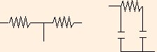
direct current (DC) circuit in which resistors are necessary: the
voltage divider:
If a voltage V is applied on the left, (in this example) a voltage V/2 is measured on the right. Voltage dividers are
the canonical example of the utility of resistance in DC circuits.
Of course in alternating current (AC) circuits,
where the voltage oscillates,
there are many more examples. Every volume control in your life is a variable resistor. The same can be said of
every tone and balance control (although not of tuning controls: those are variable capacitors). In an AC
circuit, a capacitor functions as a high-pass filter: it has less impedance (the AC analog of resistance)
to higher frequencies then to lower ones. So a variable resistor in series with
a capacitor connected to ground will shunt a variable
amount of high frequency current to ground, and you have a treble control for your listening pleasure.
The lesson here is that dissipation can be a good thing if you have it under control!
The next section is our first look at fluids.
©2013, Kenneth R. Koehler. All Rights Reserved. This document may be freely reproduced provided that this copyright notice is included.
Please send comments or suggestions to the author.
1 / Req = 1 / R1 + 1 / R2.
We can see this as follows: conservation of charge tells us that the current through the equivalent resistor must be the sum of the currents running through the original resistors. Since they all have the same voltage drop, this means that
V / Req = V / R1 + V / R2,
or
1 / Req = 1 / R1 + 1 / R2.
Two capacitors in parallel are equivalent to a single capacitor with value
Ceq = C1 + C2;
since its charge must be equal to the sum of the charges on the original two, and
Ceq V = C1 V + C2 V.
These equivalence equations generalize obviously to cases of more than two resistors (or more than two capacitors) in series or parallel.
Simplification of the Axon Circuit
Req,1 = 2 R + Rd
During the rest potential, the battery is not in the circuit:
= 82 kΩ.
Req,2 = 1 / (2 / Req,1 + 1 / Rm)
We now have a .001 μF capacitor and a 34 KΩ resistor in parallel. What can they tell us?
= 34 KΩ.
Ω F
The product RC (denoted τ) is called the time constant for the circuit. It is a characteristic value: it characterizes the behavior of the circuit. τ is numerically the time it takes for the capacitor to charge to 1 - 1/e (63.2 %) of its total charge:
= (V / A) (C / V)
Q(t) = C V (1 - e - t / (R C))
Since we have constructed this circuit as an analogy to the action potential, we see that the time constant gives us an approximation to the time between action potentials at adjacent nodes: in this case, 34 μs. This corresponds to a propagation speed of 58 m/s. Since the action potential at one node does not have to rise 63.2 mV to initiate the action potential at the downstream node, τ is an overestimate and the resulting propagation speed is low.
As you answer the questions in this applet, make note of the orders of magnitude of the answers. Compare the energy stored in
a capacitor to the energy you gain from climbing a flight of steps, and the power dissipated by a resistor to the power used by a light bulb.
Then note the magnitude of the charge stored on a capacitor; this should be comparable to the charge on your cat.
This fact helps illustrate why people who work on computers often take precautions against static: ordinary amounts of charge can damage the circuit
elements used in computers.
. . .